- 您现在的位置:买卖IC网 > Sheet目录1196 > ATAVRSB100 (Atmel)SMART BATTERY DEVELOPMENT KIT
�� �
�
�AVR454�
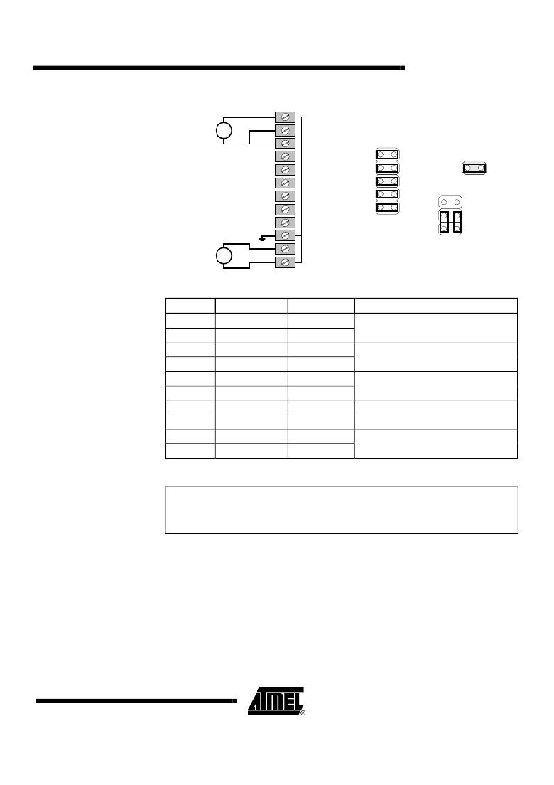
�Figure� 2-3.� CONN2� wiring� and� jumper� settings� for� battery� simulation�
�CONN2�
�V-SIM� GND�
�24V�
�-�
�+�
�V-SIM� +24V�
�FETs�
�1�
�JB3�
�J1�
�JB4�
�1�
�GND�
�±5V�
�I-SIM� +/-5V�
�I-SIM� Gnd�
�Table 2-4.� JB3: Cell voltage simulation jumper� block�
�Pin�
�1�
�2�
�3�
�4�
�5�
�6�
�7�
�8�
�9�
�10�
�Name�
�SIM-CELL4+�
�CELL4+�
�SIM-CELL3+�
�CELL3+�
�SIM-CELL2+�
�CELL2+�
�SIM-CELL1+�
�CELL1+�
�SIM-CELL1-�
�CELL1-�
�Direction�
�Usage�
�Short� these� two� pins� to� connected�
�simulated� CELL4+� to� smart� Battery�
�Short� these� two� pins� to� connected�
�simulated� CELL3+� to� smart� Battery�
�Short� these� two� pins� to� connected�
�simulated� CELL2+� to� smart� battery�
�Short� these� two� pins� to� connected�
�simulated� CELL1+� to� smart� battery�
�Short� these� two� pins� to� connected�
�simulated� CELL1-� to� smart� battery�
�2.1.4� Wiring� for� live� Li-Ion� battery� cells�
�WARNING:�
�When� using� live� cells,� never� leave� the� system� unattended� due� to� the� potential�
�hazards� associated� with� the� use� of� Li-Ion� cells.� Do� not� apply� high� charging� or�
�discharging� currents� to� the� cells� until� you� have� verified� that� all� safety� systems,�
�both� hardware� and� software,� are� functional� under� the� specified� conditions.�
�Normal� cell� wiring� is� shown� on� the� SB100� board,� labeled� as� such.� The� ATmega406�
�supports� from� two� to� four� stacked� Li-Ion� cells.� As� many� cells� as� required� may� be�
�connected� in� parallel.� A� jumper� should� always� connect� CELL1-� (CONN2� pin� 8)� to�
�Sense� Resistor� High� (CONN2� pin� 9)� to� enable� the� current-sense� resistor.� Cells�
�should� always� be� connected� on� the� lower� positions� first.� The� FET� connection�
�(CONN2� pin� 3)� should� be� tied� to� the� most� positive� cell� connection� (either� CELL4+,�
�CELL3+� or� CELL2+).�
�When� using� live� cells,� all� jumpers� should� be� removed� from� JB3.� Additionally,� the�
�sense� resistor� should� be� connected� to� the� CCADC� inputs� by� shorting� JB4� pins� 1-3�
�and� 2-4.� It� is� possible� to� use� the� Current� Simulator� while� connected� to� live� cells� simply�
�5�
�2598C-AVR-06/06�
�发布紧急采购,3分钟左右您将得到回复。
相关PDF资料
ATAVRSB200
KIT EVAL FOR AVR SMART BATTERY
ATAVRSB201
KIT REF FOR AVR SMART BATTERY
ATDH1150USB
ACCY USB CABLE JTAG ISP AT18F
ATDVK90CAN1
KIT DEV FOR AT90CAN128 MCU
ATEVK1104AU
KIT EVAL AT32UC3A3256AU
ATEVK1105AU
KIT EVAL AT32UC3A0512AU
ATEVK525
ADD ON KIT FOR STK525
ATEVK527
KIT EVAL PWM AVR USB 4 SERIES
相关代理商/技术参数
ATAVRSB200
功能描述:开发板和工具包 - AVR Development platform for SB20x ref design RoHS:否 制造商:Arduino 产品:Evaluation Boards 工具用于评估:ATMega32U4 核心:AVR 接口类型:I2C, UART, USB 工作电源电压:6 V to 20 V
ATAVRSB201
功能描述:开发板和工具包 - AVR Development kit for ATMEGA16HVA RoHS:否 制造商:Arduino 产品:Evaluation Boards 工具用于评估:ATMega32U4 核心:AVR 接口类型:I2C, UART, USB 工作电源电压:6 V to 20 V
ATAVRSB202
功能描述:开发板和工具包 - AVR Battery Mgmt Eval kit for ATMEGA32HVB RoHS:否 制造商:Arduino 产品:Evaluation Boards 工具用于评估:ATMega32U4 核心:AVR 接口类型:I2C, UART, USB 工作电源电压:6 V to 20 V
ATAVRSBIN1
功能描述:多功能传感器开发工具 9DOF Inertial Sensor Board 1
RoHS:否 制造商:Texas Instruments 工具用于评估:LMP91200 接口类型:SPI 工作电压:1.8 V to 5.5 V 最大工作温度:
ATAVRSBIN2
功能描述:多功能传感器开发工具 9DOF Inertial Sensor Board 2
RoHS:否 制造商:Texas Instruments 工具用于评估:LMP91200 接口类型:SPI 工作电压:1.8 V to 5.5 V 最大工作温度:
ATAVRSBLP1
功能描述:光学传感器开发工具 Ambient Light and Proximity Snsr Brd
RoHS:否 制造商:ams 工具用于评估: 接口类型: 最大工作温度:
ATAVRSBPR1
功能描述:压力传感器开发工具 Barometric Pressure Sensor Board 1
RoHS:否 制造商:Freescale Semiconductor 工具用于评估:MPL3115A2 接口类型:USB 最大工作温度:
ATAVRSECURITYX
功能描述:安全/ 验证开发工具 Security Module Kit for Xplain Series
RoHS:否 制造商:Digi International 产品:Development Kits 工具用于评估:XEB-AW140 接口类型:SPI, USB 工作电源电压:3.1 V to 3.6 V